the Stabilizer Problem
Stabilizers have long been the great unsolved problem in the world of keyboards. Their function is straightforward; they prevent longer keys (such as the spacebar) from seesawing upward at one end when the opposite end is pressed down. Current solutions serve that purpose well enough, but the issue is: they all sound awful. Taeha Kim's face in response to the rattle of an unmodified traditional stabilizer—in a video it amuses me to note has been viewed millions of times—sums up how all of us keyboard nerds feel.

For decades this has been the core absurdity of luxury typing: you can buy a $4,000 hyper-engineered super-premium board with exotic materials, rare hybrid switches, hidden fasteners, leaf springs, and custom gaskets interfacing every surface. Yet among its most critical components can be found a fundamentally flawed mechanism that has seen little refinement since its inception.
Hobbyist modders thus spend long hours hand-lubricating and tuning their stabilizers to eliminate rattle, painstakingly brushing high-viscosity grease into the interstices between parts.
This chore requires a delicate dance between desirable dampening and unwanted key sluggishness. It works, but it's an ugly hack—an acoustic band-aid that is tricky to perform consistently and whose efficacy erodes over time as the grease seeps away.
Because it is fiddly and annoying, it is easy to mistake lubing for a fancy atelier process that is part of the very definition of a high-end keyboard. But I've always suspected that it's really just a ham-fisted way to compensate for bad engineering—effectively, a concession of defeat. After five years inquiring deeply into this question, including multiple patents issued and pending and project expenses running well into the six figures, I can now with some confidence confirm those early suspicions.
Especially since the band-aid solution is more or less serviceable, though, one might reasonably ask about why anyone should care so much. The answer in my case is that I have for some years been on a mission to create what is, to my sensibilities, the perfect luxury keyboard—one that anyone, whether a hardcore hobbyist or keyboard neophyte, can buy, plug in, and immediately and indefinitely enjoy. That keyboard, called the Seneca, is meant to be my expression of the best typing experience obtainable, and every component of it is fully custom to my original designs. It's about some very sentimental artistic and emotional goals, and so it's emphatically not about engineering perfection or technical accomplishments for their own sake. But, for a project in which I've invested so much of myself, I simply felt that poorly engineered stabilizers could have no home.
For this reason, I’ve always known that noisy stabilizers were a problem that Norbauer & Co. would somehow eventually have to invent its way out of, having to find an approach better than anything that yet existed. I had done something similar before with the Heavy Grail, heedlessly setting off to conquer a technical mountain that would prove a far steeper climb than I would have imagined, but ultimately successfully doing what I set out to. What I didn't realize at the outset this new journey, of course, was that I would—in some dubious mixture of folly and obsessive perfectionism—end up uncontrollably traversing its difficult terrain three times over.
As you'll see, I brought no particular engineering brilliance to this problem and thus can claim no glory from any success that may have resulted. What got me to the ultimate solution was little more than recklessly training a personal cash bazooka on the question, and being doggedly, irrationally—truly insanely—persistent in my conviction that there must be a perfect answer.
The basic problem and some terminology
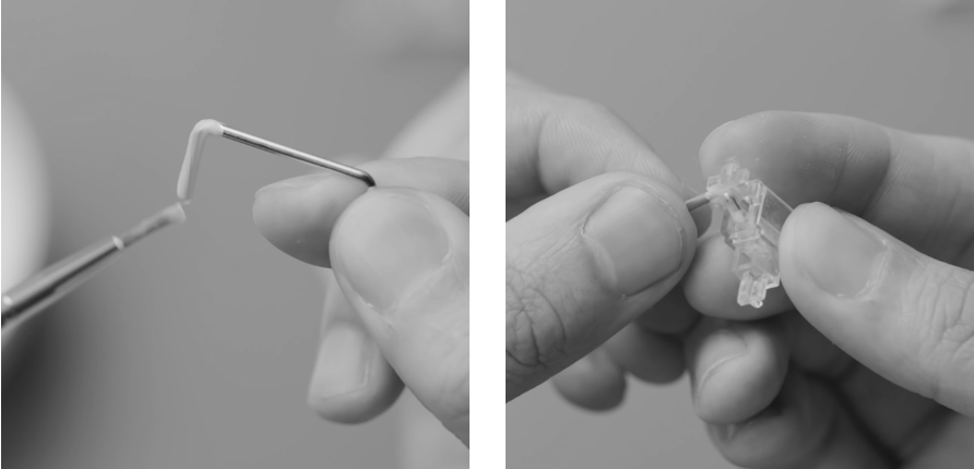
Below is the architecture of a traditional Cherry-type stabilizer. A keycap is connected to two sliders via a press fit onto their cruciform mounting points. Those sliders move up and down with the key travel, and a spring-loaded switch (also pressed into the keycap) is situated between the two stabilizing ends. A rotating wire clipped into the stabilizer housings has two extension arms that insert into the two sliders, pulling them up and down together in tandem and thus creating the anti-seesaw effect.
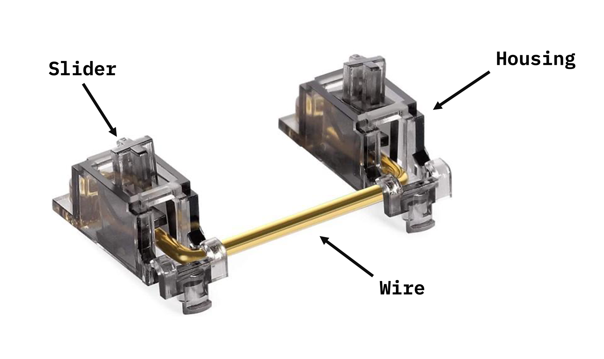
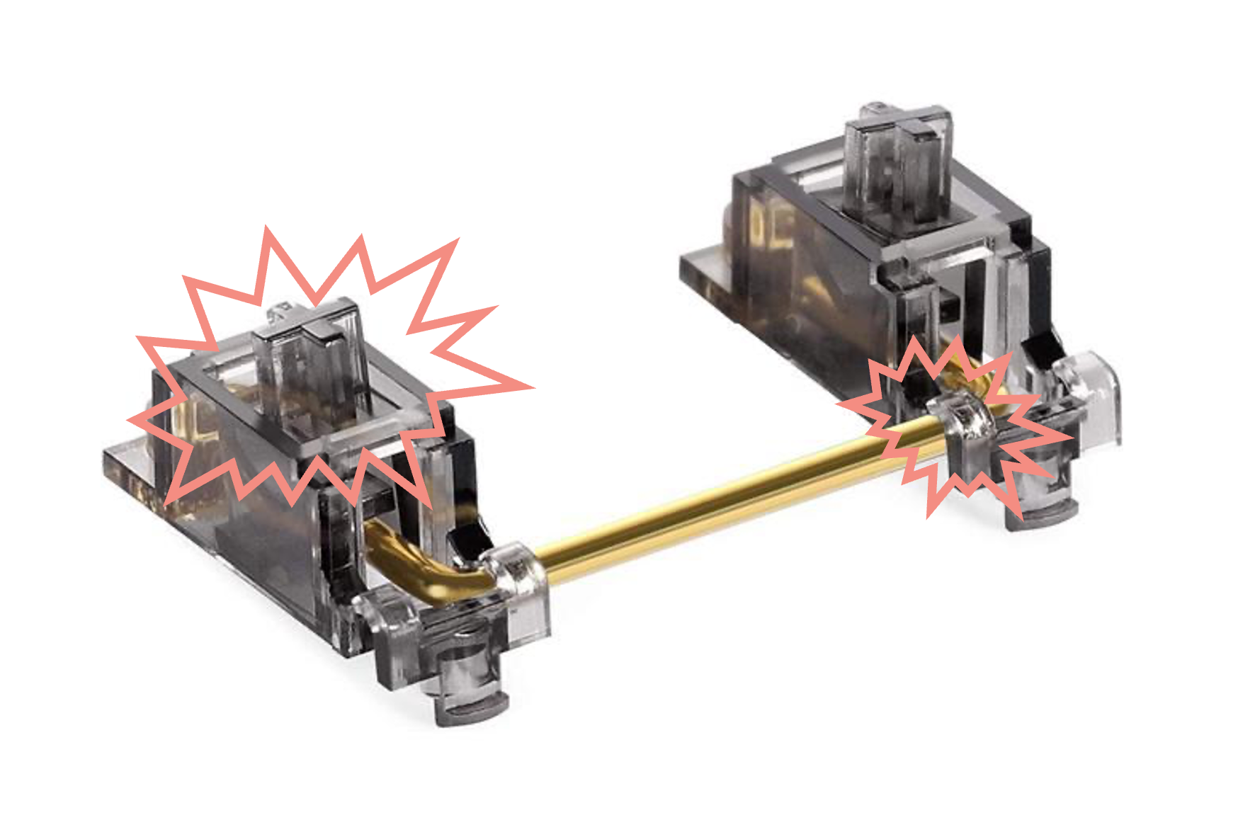
There are two primary sources of unwanted sounds. I'll formalize some keyboard community terminology here by calling the first rattle, which refers to the sound of the hard wire linkage striking against the hard plastic surfaces in the interior of the slider. This is by far the most prominent and displeasing source of stabilizer noise.

The second more subtle source of unwanted sound can be termed ticking, and it refers to the sound of either the slider or wire moving against the housing.
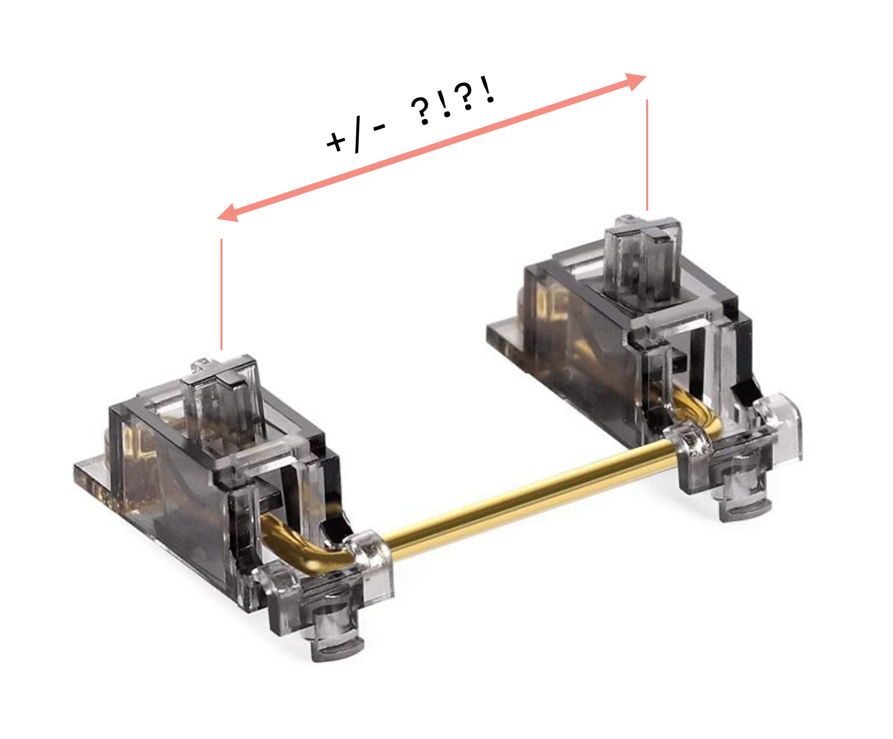
There is one additional complicating factor, which is that long keys like spacebars frequently vary between manufacturers in their stem spacing length. Any widely applicable stabilizer design must therefore accommodate a remarkable degree of dimensional variability.
Paradoxes and contradictions
Armchair community speculation—including indeed my own in the past—has always held that the unwanted noise of stabilizers comes from "loose tolerances," with the implication that this is due to manufacturer laziness or cost optimizations. "Tolerance" is an engineering term with a real and precise meaning, but when used in this context what people generally really mean is "loose fits." We're talking here about having large gaps between the moving parts that touch each other.

It is, in a sense, not a fundamentally untrue observation that fits are an important part of the issue. But were it down to gap size alone, changing a few numbers on a spec sheet would have done the trick, and the problem would have been solved long ago. The fact that it hasn't, in fact, been solved long ago is therefore instructive.
Indeed, if we are to design a perfect stabilizer, we must first confront a contradiction in our requirements: we need the mechanism to be at once loose and tight. It must be "tight" in the sense that there must be no backlash or movement between parts that could create unwanted sounds, but also in the sense that it must accurately and with minimal wobble perform the anti-seesaw action that is the foundational premise of a key stabilizer. These objectives typically require small gaps between mating parts. But the stabilizer mechanism must at the same time also be "loose" in the sense that the key must move up and down very freely to avoid any chance of binding, which is when the key ceases to move due to accumulated forces within the system (most commonly causing the keycap to fail to pop freely back up after being depressed). To achieve this objective, large gaps between mating parts are required. Thus the contradiction.
In fact, the phenomenon of binding—or the tension between the objectives of small gap size and free movement—turns out to be the primary obstacle to the creation of a perfect stabilizer. There are standard ways of engineering around binding issues, and we'll explore in the next section why those are challenging for stabilizers, but for now it's enough to observe that inherent in our design requirements is the sort of thing that makes for the most difficult of engineering problems: two seemingly incompatible design objectives.
Designers of existing stabilizers seem to accept as given the incompatibility of those objectives, understandably then choosing to favor a key that actually moves up and down (loose fits) over one that is unusable but pleasantly silent (tight fits). And this is why we find in all existing stabilizers large gaps and rattle—and a need for the unhappy grease band-aid.
Bearing ratio and the binding paradox
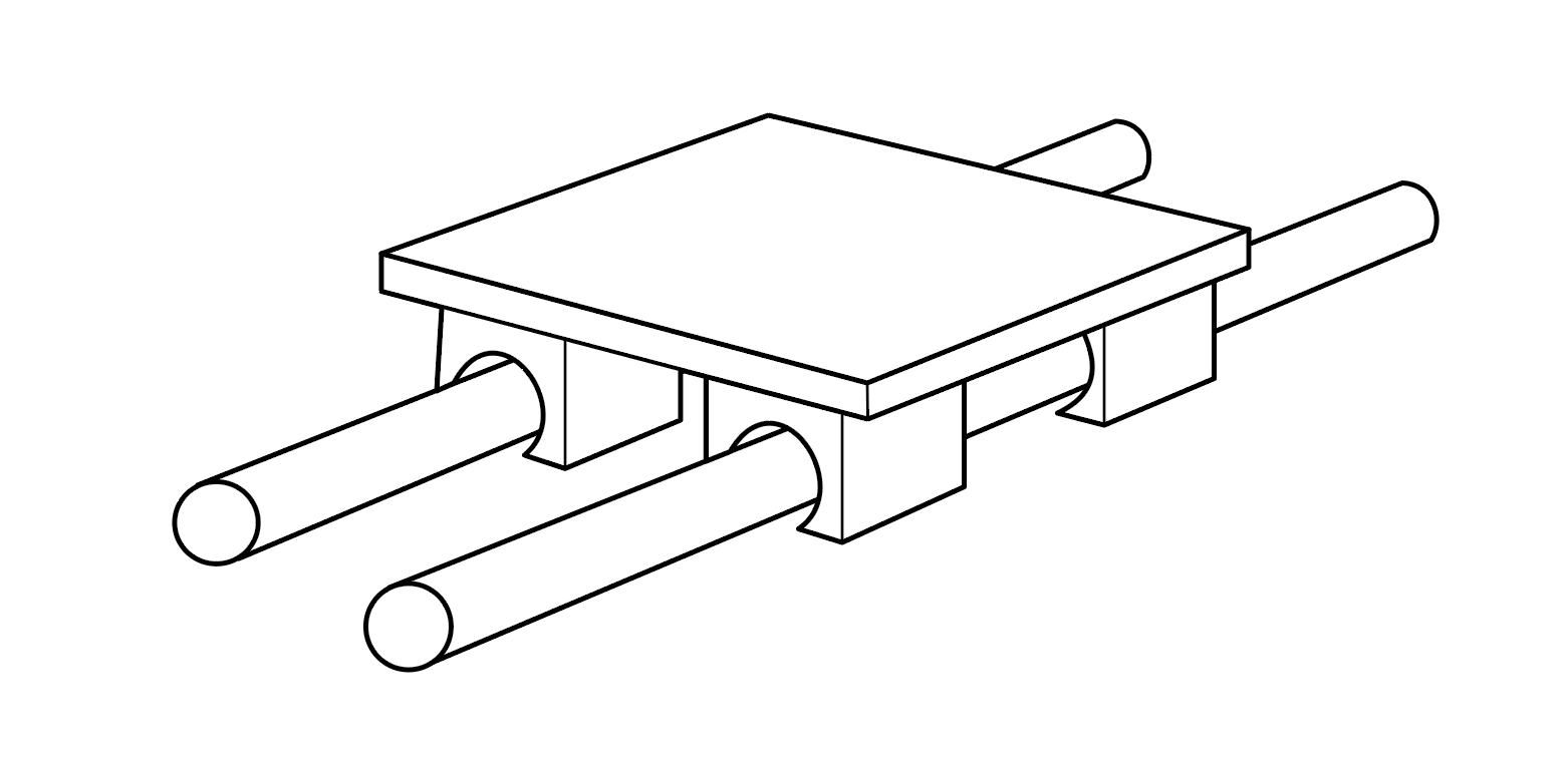
It may not be obvious on casual inspection, but a key stabilizer is essentially a sliding linear bearing: that is, a mechanism to provide unrestricted translational motion along an axis, while restricting motion in other axes. One common example of a linear bearing would be a rectangular carriage that moves along the length of two cylindrical rods.
Linear bearings are well characterized in the world of mechanical engineering and are subject to two important design considerations known as bearing ratio and binding ratio. These consider the geometric relationship of variables like the distance of the bearing load to the length of the bearing. As with all engineering rules of thumb, these ratios give a practical handhold on much more complex points of underlying physics. Rather than delve here into force vectors and friction calculations, which I don't understand fully myself anyway, suffice it to say that when the rules are violated, bearings become very sensitive to friction and manufacturing variation, and the accumulation of forces inevitably leads to binding and other performance problems (See Design of Machinery for a more in-depth discussion.)
It's enough to know that the geometric constraints of a traditional stabilized key switch are a particularly bad scenario for the rule-of-thumb ratios: a very short travel distance, with both a long "moment arm" (in this case, the keycap) and large diameter relative to the bearing length. These are all the exact opposite of what we want for good linear bearing performance, and thus what we can expect from the theory is exactly what we find: most solutions are extremely sensitive to manufacturing variation and prone to binding.
Product development via dolorosa, in three acts
Of course, I didn't really understand any of this when I embarked on an attempt to solve the stabilizer problem. I have no formal training in mechanical engineering, but I tend to believe in the power of empirical tinkering, and have often been surprised by how far that has been able to get me in many domains of life. It was some combination, then, of ignorance and yolo audacity that allowed me to think it could somehow be an easy problem to solve.
Another reason for confidence was that, at the time I started this project (and still to some extent), most companies operating in the mechanical keyboard space with the finances to produce expensive injection molding tooling were large mass-market consumer electronics brands, typically selling keyboards in the $100-200 range. It was therefore reasonable to infer that many design choices would have been made in the service of cost optimizations at large scale over extremely fussy matters of acoustic nuance to which most casual retail consumers would be completely deaf anyway. So I naively assumed that, merely by adopting a different strategy—choosing to prioritize performance and damn the unit costs—I would easily go farther than others who had preceded me. ("Just tighten the tolerances.")
I knew in any case—if you'll forgive the trite observation—that from failure at least comes knowledge, and often the most important part of getting somewhere is putting a first foot in front of the other. So I set the following design objectives for a Norbauer-type stabilizer:
- Total elimination of rattle and ticking, without recourse to grease or lubrication
- Accommodation of dimensional variability across a wide range of keycap stem spacings (i.e., support for various keycap vendors)
- Free and smooth movement without any binding
- No significant alteration of the force curve of the switch when used without stabilization
- Compatibility with my own capacitive switches, which have a larger footprint than Cherry MX
- Tool-free install and removal of keycaps
- Compared to normal actuation, installation and removal of a keycap is a fairly violent process. There need to be end stops beyond normal switch travel, in both directions, allowing the keycap to be pressed into place and removed. And that process cannot deform the stabilizer wire linkage.
It should be noted that, by the time I began this project, the Seneca keyboard for which these stabilizers were intended had already surmounted a number of hard engineering hurdles, not least of which was the creation of my own capacitive PCB platform and firmware. The overall keyboard was, as I perceived it then, already 90% done. The stabilizers were merely "the last little 10%" to get the whole product to be perfect.
Act I: Tinkering and Bricolage
Oddly, my first foray into this problem around 2019 began with the realization that a stabilizer is in fact a linear bearing (without knowing any of the corresponding design rules of thumb). At a manufacturing trade show, I had seen some interesting "self-lubricating" plastic bushings for linear bearing rods, made solid out of a special injection-molded polymer, and so it occurred to me to give those a try. These seemed like a good option because the tiny work envelope of keyboard stabilizers requires much smaller parts than are typically manufactured as ball or roller bearings, which would otherwise be the natural bearing type to use for something like this. I figured if we were just to create a cruciform mounting point to insert some low-friction cylindrical rods into the keycap stems, make those rods with precision, and then insert those rods into parallel bushings inserted into a switch plate, all would be well; problem solved. I knew from the spec sheets that these bushings required a particular (tight) tolerance range for a free-running clearance fit, and in attempting to make rods to fit into them (and attach to the keycap stems) I quickly learned the first lesson of how difficult the road ahead would be.
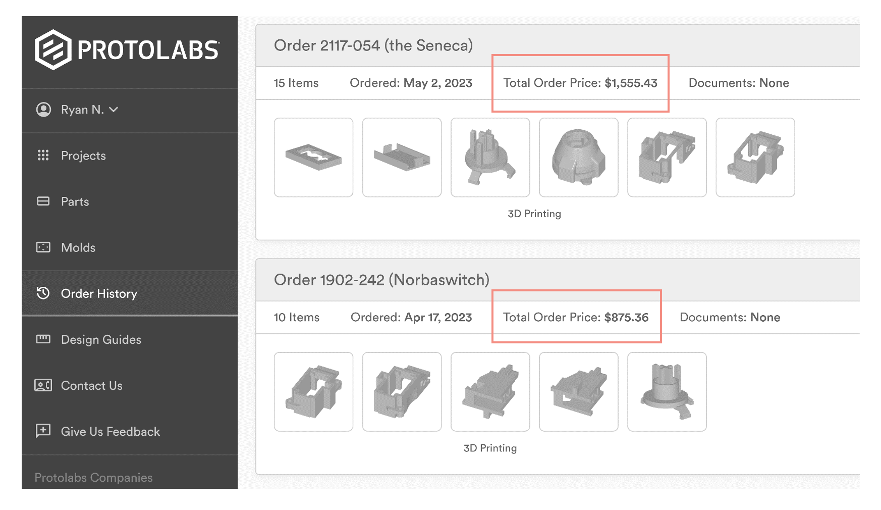
Tiny parts are extremely expensive to prototype with accuracy and good surface finishes. The only machine shop I could find that would make the prototype parts for me was one that specialized in manufacturing for Swiss watch makers, at the cost of some thousands of dollars for just a few test samples. This is a fact I would go on learning as I would continue to refine my experimental designs. Even 3D printed parts made to the right tolerance and surfaces I needed to get good information would be insanely expensive to produce, and thus the cost of iterating much higher than if the parts didn't have such minuscule mission-critical features. The below screenshot shows orders of parts that that, together, were all small enough to fit in the center of the palm of my hand, and I'd be embarrassed to admit how many such orders I've placed over the past few years.
I did also eventually get a Formlabs SLA printer for in-house prototyping, but the surface finish and fine details were only good for very rough initial concept exploration, requiring the outlandishly expensive Microfine printing process above for more detailed studies. SLA resins are all very susceptible to abrasion and so only a few switch actuations of the parts sliding against each other would change their dimensions and roughen their surfaces. Even though the finishes right out of the printer were as good as almost any 3D printing technology can yield, it was still much rougher than actual injection molded parts. This would greatly increase friction and exaggerate binding issues, so I had to brush XTC-3D carefully onto the surfaces to get something even approaching a production surface and thus a more accurate sense of binding. Maddeningly, this would in turn throw off the part dimensions and tighten up the gaps, itself an independent cause of unrepresentative binding. Test molding the parts in thermoplastics was an option, of course, but often at the cost of more than $10,000 per part, and quick-turn companies like Protolabs are extremely limited in their abilities to make parts with side actions and high gloss surface finishes, so most of what I wanted to try could only be done with very slow test molding through traditional factories (a process generally with a multi-month turnaround).
At any rate, after the high-precision machined parts arrived months later to test out my genius cylindrical bearing plan. Here is how that went:
What was I was experiencing without realizing it were the effects of an awful bearing and binding ratio along with kinematic over-constraint (on which more later). All I knew at the time, though, was that it wasn't an auspicious beginning.
I floundered around for months, talking to various mechanical engineers and examining if there might be ways to go back to the basic existing stabilizer paradigm and perform some modest tweaks to mitigate sound issues.
A second dead-end, after consulting with an acoustics engineer, was a diversion into materials science, as I tried to figure out if thermoplastics with different properties (for use in molding the slider) could dampen the acoustic effect of contact between it and the housing or wire. I experimented with 20 different materials, allowing for 190 different combinations. I quickly learned that there was an another infelicitous tradeoff here, offering only a choice between good acoustic dampening accompanied by problems of drag and abrasion (as with HDPE, LDPE, TPE, and PP), or good resistance to abrasion and drag with awful acoustics (as with PA66, POM, PBT, and ABS). I even used urethane vacuum casting to make some prototype sliders in a TPE-like polymer, with predictable results: a squeaky, draggy mess—to say nothing of the impossibility of fitting a keycap onto a squishy cruciform stem.
One later concept I came upon, which wasn't entirely off base, involved the use of a Scotch yoke design otherwise similar to existing stabilizers. By inserting the wire from the side and allowing it to rotate in a slot within the slider, it would be theoretically possible to have a smaller clearance gap between slider and wire than in front-insertion traditional stabilizers.
This got acceptable results, but it required very large gaps between slider and housing to get free movement without binding. Rattle was slightly improved, but ticking was, if anything, worse than on traditional stabilizers. And, every time I would tighten up the interfaces to improve acoustics, the system would bind up.
I then turned my attention back to a more traditional front-insertion design and focused on tightening gaps and thickening walls.

You may also have noted the use of spade-like mounting point for the keycaps, which was an attempt to accommodate for keycap width variation. Among other issues, the main trouble with this solution is that it's possible for the sliders to go into the keycaps at weird off-axis angles, and they don't always self-straighten. This puts additional forces into the system that lead to binding.
I also simultaneously tinkered with adding a rubber overmold to the interface between wire and slider in hopes of dampening the source of rattle, which was perhaps the most successful of my early experimental ideas.

With a sufficiently polished mold and shiny surface finish for the rubber overmold on the wire, it was actually possible to get decent acoustic behavior out of this approach. Putting one's ear close to the stabilizer in operation, however, a bit of squeak was perceptible. This could be mitigated with a dry graphite lubricant, but that would likely wear away with time and defeat the whole purpose of lubricant-free stabilizers. I was also concerned about the rubber abrading over time and a corresponding degradation of performance. Ticking was also still present, of course, since there was no rubber between housing and slider or wire, and I had learned previously that adding it would introduce drag and binding. Another issue we encountered was that the process of overmolding the rubber onto the wire would slightly—and unreliably/randomly—throw the wire dimensions out of tolerance, leading to yet another elusive source of binding.
In all this experimentation, a pattern began to emerge of three opposed concerns, where optimizing one always seemed to mean sacrificing the others:
- Good acoustics without rattle or ticking (small gaps, a.k.a. "tight tolerances")
- Good mechanical performance without binding
- Support for keycap width variations
Whenever I would tweak toward one of these, the others would become unacceptable.
One recent attempt at solving the stabilizer problem, Staebies, creatively redefined the problem and decided to sacrifice point #3 in favor of the others. This meant tightening gaps between slider and housing in a way that would cause binding on many keycaps but that would work well on the relatively narrow dimensional range of GMK keycaps. But that cleverly evasive solution only underscores the seemingly ineluctable set of tradeoffs above.
All I could hope for, I figured, was to find some kind of optimal sweet spot between the three tradeoffs. It took a lot of delicate titration to get the gaps just right (even the diameter of hole in the the wire clip had a huge effect), and it all took years, but with lots of stochastic trial and error, I did actually end up getting pretty close to a 90% solution. I didn't fully understand the tolerance range that would or wouldn't lead to binding, but I did come up with a set of nominal gap sizes that, when combined with an overmolded wire, seemed to lead to acceptable performance. That is: what I had was actually better than any unlubed stabilizer on the market and thus I had, in a way, actually solved the problem—in a way that no one had, to my knowledge, accomplished up to that point.
The following 3D printed prototype used these features and can be heard operating below completely without lubrication:
Many keyboard enthusiasts whom I showed the prototype were amazed, but I remained morose. It was a 90% solution (for the last 10%, you will recall, of a keyboard that was otherwise itself "90% done"). That last 10% gnawed at me. I had made too many compromises along the way to where I was. And the whole point of the project was a no-compromises stabilizer for a no-compromises keyboard.
Act II: Kinematic and Tolerance Optimization within the Existing Paradigm
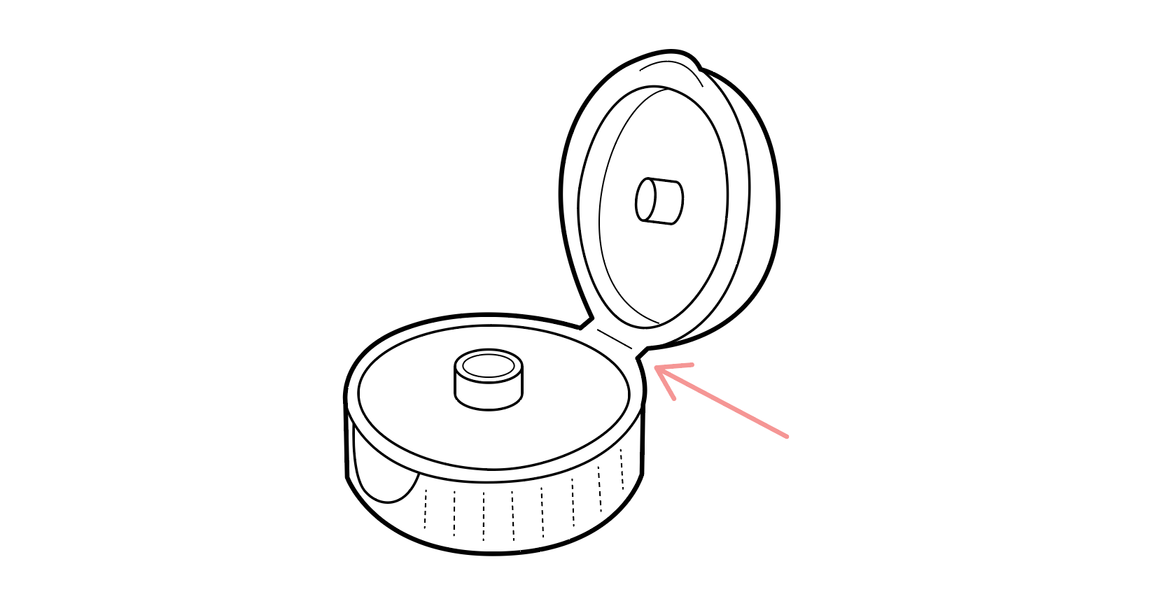
I puzzled and agonized for months about what to do, when I by chance stumbled into some information about compliant mechanisms. The more I read about the properties of compliant mechanism design, the more I realized, at least on paper, they provided exactly the properties that I wanted in a stabilizer. Compliant mechanism design takes an assembly that would otherwise consist of multiple parts and joins them together into a single part that instead uses flexing inherent in the material to facilitate movement. A simple everyday example of a compliant mechanism is the flexible "living hinge" you might find on the cap of a moisturizer or sunscreen bottle, which acts as a single-part replacement for the sort of multi-part pin-joint hinge you might find on a door.
Since all of the acoustics issues in stabilizers arise from separate parts hitting against each other, making a single-part stabilizer from a compliant material seemed like a very promising avenue of exploration. This inspiration did actually end up being an indirectly fruitful one, but as the general theme of this project goes, there was far more nuance to the matter than I had at first suspected.
The main issue with sophisticated compliant mechanism design is that it's a relatively new discipline, and most of the people doing it at the moment are still in academia. I spent months trying to convince some of the big names in the field to consult for me on the project, but we were never able to work through the irritatingly restrictive IP agreements they had with their employer institutions, which apparently claim any and all of neural firings of professors—on or off campus—as their property. That was several more months of dead ends.
I was eventually able to find one commercial consulting firm that claimed expertise in compliant mechanism design and hired them to do an initial study for $12,500, to be paid up front. In long Zoom calls and in-person meetings they endlessly and insufferably sang their own praises, insisting that their engineering genius would have us at the "Hermès of keyboards" in short order. (I should have listened to my initial bad feeling about those interactions, but they were the only people I could find doing compliant mechanisms who would answer my emails.) I gave them one month to show me a working proof-of-concept prototype, at the end of which, alas, all I got was a lot of idle speculation and what was effectively a $12,500 animation:
Their guess was that this (still very half-baked) mechanism would at least probably perform the basic stabilizing function, but that it would likely need to be made in metal, using a number of extravagant manufacturing processes at an unknown cost. More problematically, they also speculated that it would likely make a "ka-thunk" sound when actuated. Of course there was no way to know any of this without a physical prototype—nor was there any concrete plan for making one on a reasonable timeline. So I fired them.
I subsequently learned was that a compliant mechanism configuration like the one they were proposing would also have a variable force curve, with resistance mounting with the distance traveled as the hinges compressed, leading to an unacceptable "jelly like" feel to the key. So much for that idea.
However, in researching compliant mechanisms I stumbled into a page referencing the topic by the Danish product engineering firm RD8. I noted that they had done product development work for luxury consumer products brands like Audi and Bang & Olufsen and also Lego, with its already famously sophisticated in-house engineering abilities.
I frankly figured they would 1) never respond to to an inquiry from a small business like mine and 2) even if they did, would be utterly beyond my already fairly irresponsibly high appetite for costs, but I gave it a shot and cold emailed them anyway. I got a quick and friendly reply from Markus, one of the founders of the company and we hopped on a Zoom call. He explained to me that RD8 specializes in solving hard product development problems and engineering "satisfying" mechanisms for high-end consumer and industrial products, both of which were precisely what I was looking for. He seemed very compelled by the idea of my work and the brand I was building—seemingly excited to work on a more creative and wacky project than what they typically see from their more straitlaced corporate and medical clients. I found him and his team to be singularly intelligent, candid, and competent.
In order to do what they do, RD8 have developed a comprehensive conceptual framework for designing products, which adheres to a school of engineering, Japanese in origin, known as robust design. There are many aspects to the RD8 approach to product design, and they teach entire courses—some of which I've taken myself—to already-seasoned engineers in these techniques, but one area is of particular of interest to us here: kinematics.
Kinematic analysis looks at the intended movements (or "degrees of freedom") of a mechanical system and ensures that only the minimum number of features are present on the parts to achieve exactly the intended behavior. This is because adding any additional constraints beyond the minimum necessary leads to phenomena like binding, chatter, rattle, drag, and abrasion. Sound familiar?
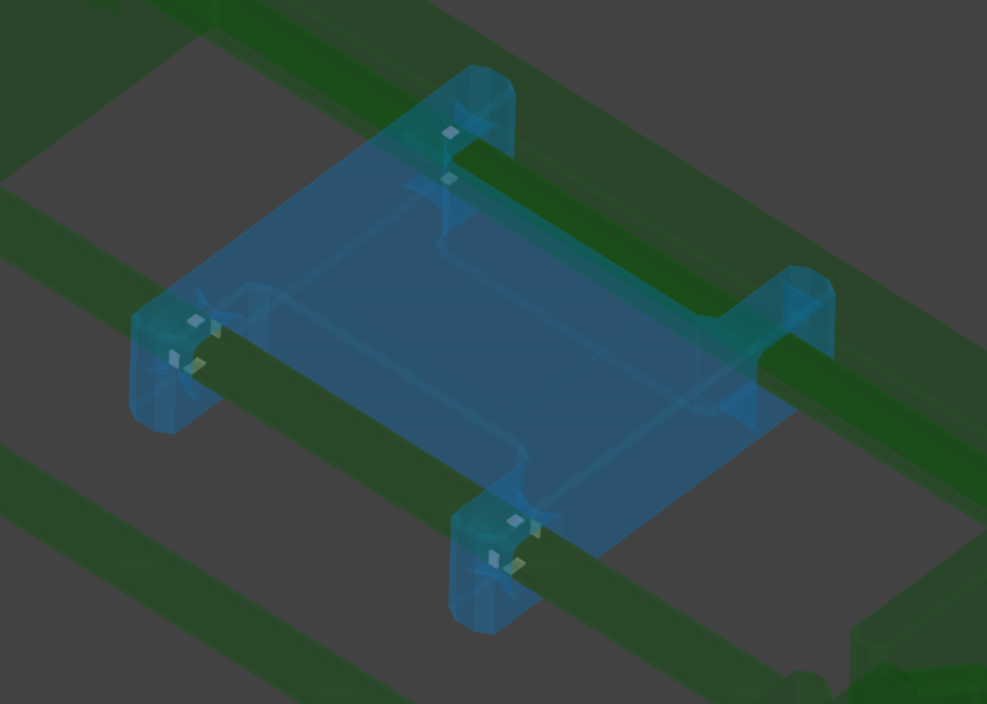
To demonstrate the idea, let us return to the concept of a simple linear bearing sliding along two rails that I introduced before. In a classic RD8 example below, there are two such sliding carriages: one magenta and one blue.

Each of them runs along two metal rods, which are set up in a green test fixture that, by use of a mechanism at the front, can move each pair of rods from perfectly parallel to slightly misaligned. This type of slight misalignment represents the type of variation one typically experiences in the manufacturing of injection molded products—or any number of other types of aberrations such as the introduction of friction into the system through poor surface finishes, etc. When we activate that mechanism at the front and slightly mis-align the rods, taking the system out of the "perfect" state, the magenta carriage immediately binds up, whereas the blue one continues running freely.
This is because the magenta carriage, even though it using a very common design for such bearings, is actually kinematically over-constrained. It uses four cylindrical mating surfaces to run along the rods, as shown in white below. The redundant constraints unnecessarily make the system highly sensitive to manufacturing variations or other sub-optimal mechanical conditions.

A kinematically optimized version of the same design would look like the following blue slider with white contact faces against the rod. It has only exactly the number of contact surfaces—and no more—that are required to constrain the desired degrees of freedom. Note that the bottom-right bushing makes no contact whatsoever with the rod, and the top-right bushing does so in only two targeted spots (preventing rotation of the carriage about the axis of travel). This makes the system highly robust to variations but it still exactly and smoothly performs the designed mechanical movements. That is: it is both tight and loose.
The folks at RD8 report that nearly every single design that comes to them for improvement—from mechanical engineers at major global corporations—are over-constrained in some way. So, while this might seem like an Engineering-101 concern, it's actually a hard and subtle matter to get exactly right—and one that is frequently overlooked even by professionals. Including, indeed, by whoever it is that designed the original Cherry stabilizer and all the downstream engineers who copied it.
Without diving too deep into the arcane details of the kinematic analysis, my "90% good" stabilizer design, which was kinematically equivalent to traditional Cherry stabilizers, actually scored pretty well.
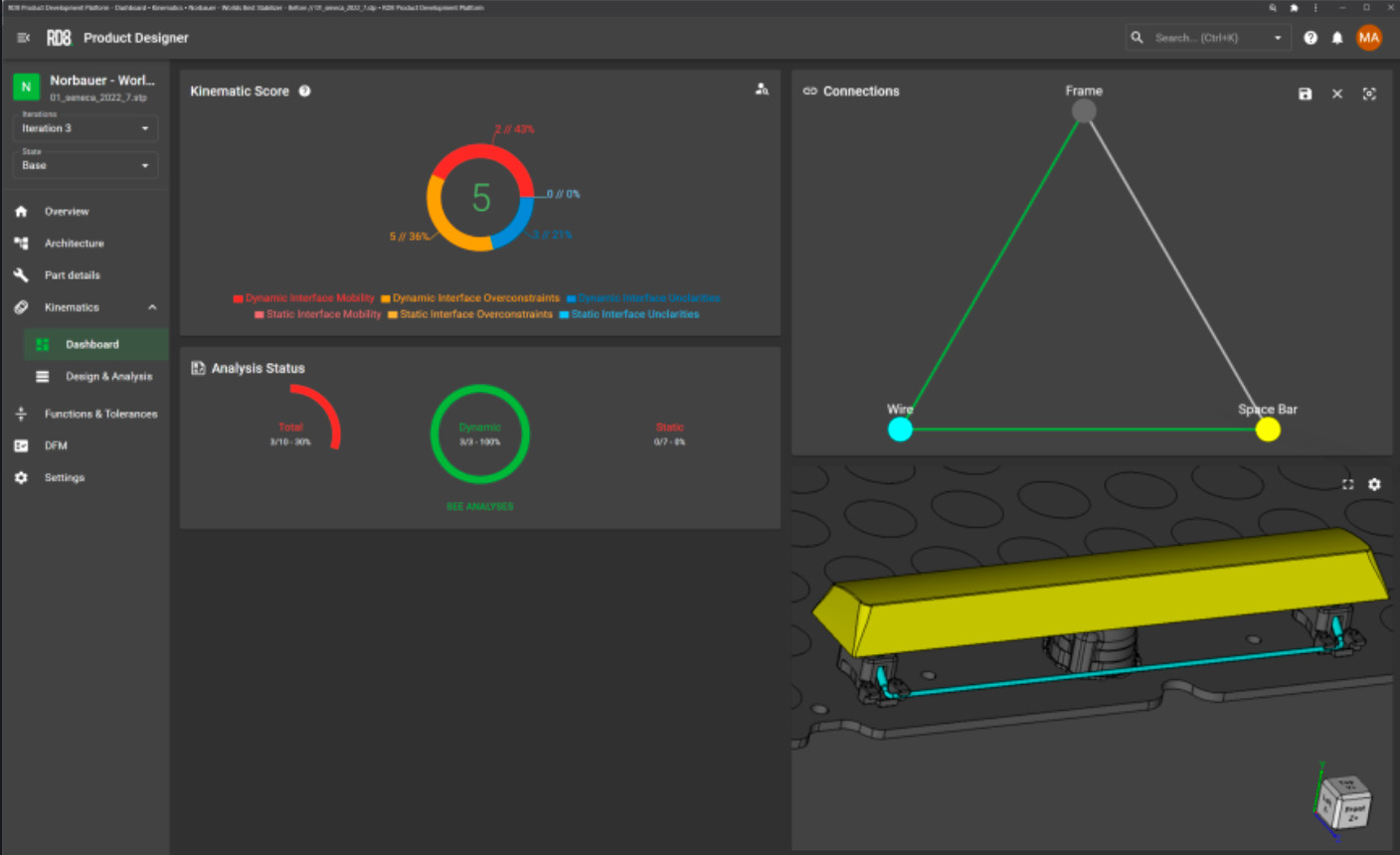
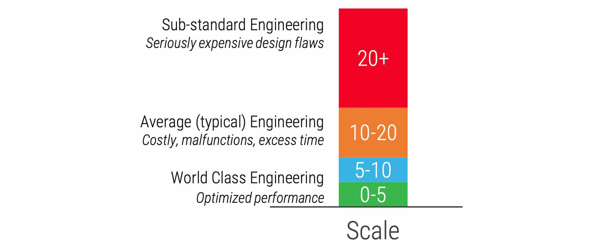
A score of 5 put me in the "world class engineering" category within RD8's analytical system.
But the issue was that for stabilizers we're working within the context of a very challenging bearing/binding ratio and a long list of strict (conflicting) requirements, which means that "extremely good" wasn't good enough to get us everything we wanted. We needed to go from "kinematically good" to "kinematically perfect."
Markus therefore suggested that we set aside a full compliant-mechanism idea, which, while within their abilities, would be much more expensive and risky to develop. Instead, he suggested we simply focus on making a traditional multi-part design that wasn't over-constrained. We agreed on a one-month sprint for around the same cost as the compliant mechanism consulting firm and agreed that the criterion for proceeding to subsequent sprints would be the same: a physical proof-of-concept prototype at the end of the four weeks.
After a bit of study Markus and the engineer he put on the project, Bo, came to me with two viable design strategies, both sound in their approach but one less risky and more conventional and one more risky but more ambitious.
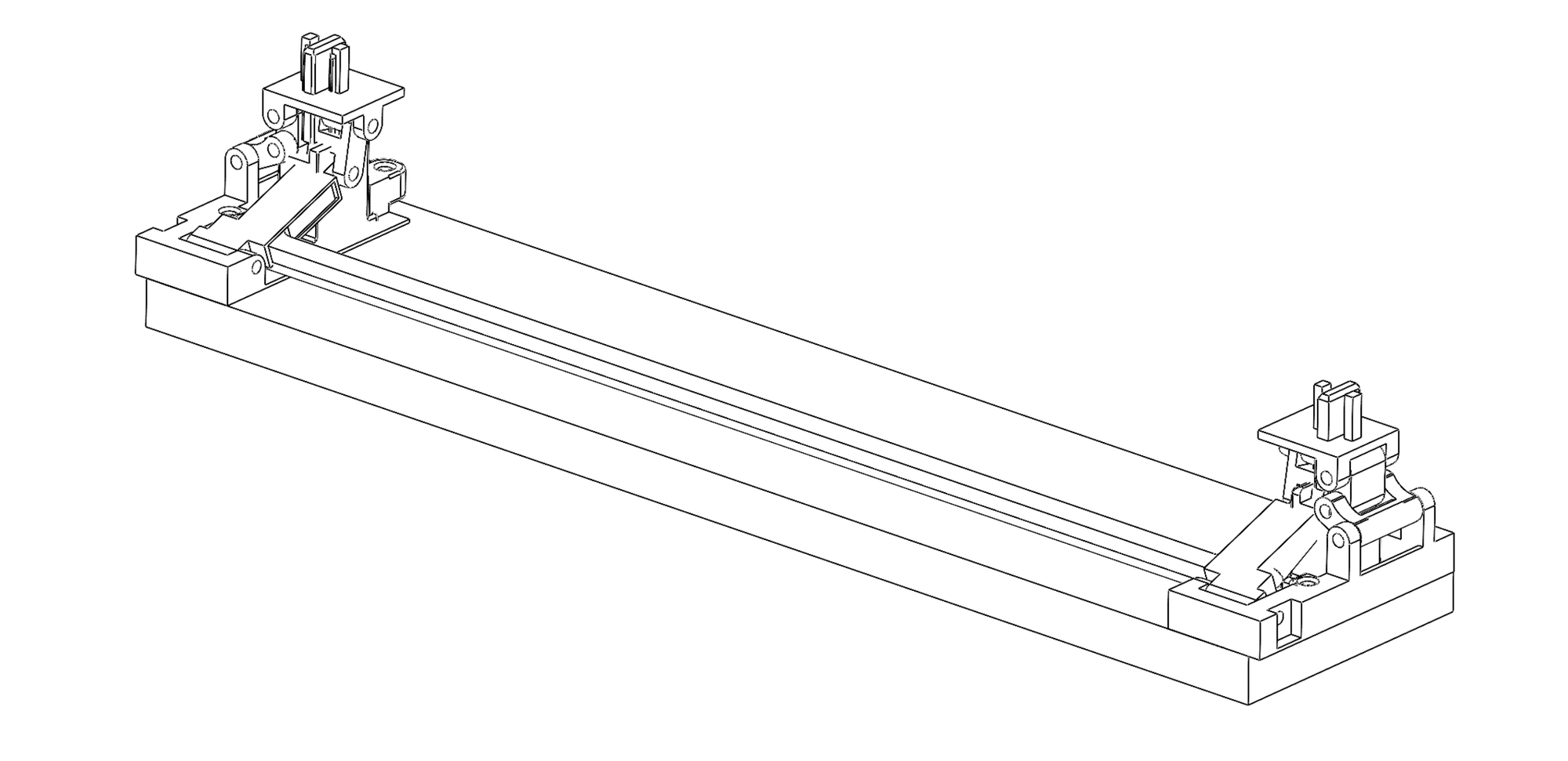
The first option was a slight modification to the existing Cherry MX paradigm that was optimized for a kinematic score of a perfect 0, primarily focused on removing over-constraints, tightening tolerances, and mitigating bearing ratio issues as much as possible. We'll call this the tongue-in-groove stabilizer, for which they presented the following concept.

This approach would require a lot of clever internal tricks to get it to perform to acoustic perfection, which I'll detail below. But there was also a second concept, which for now we'll call the pin-joint stabilizer. It was an intricate clockwork-like mechanism, with many moving parts and multi-jointed hinges, initially mocked up as follows.
While it looked really cool, and I knew it had some technical points in its favor, the complexity and high part count scared me. I was already nervous about figuring out how to swing the cost of the many injection molding tools that would be required to produce the Seneca (at tens of thousands of dollars for each unique part), and the pin-joint solution had over twice as many parts as the tongue-in-groove option. It all just seemed too risky and uncertain, so we decided to go with the more straightforward option.
By the end of the first sprint, RD8 had a physical prototype that did everything we wanted. It took a number of additional sprints to get to the point of a fully-polished and production-ready design, but it was clear that their magic was going to work.
Perhaps the first and most critical innovation was solving the problem of over-constraint, because that bought technical breathing room to add features to deal with noise and keycap variation. And that solution lay in the tongue-in-groove geometry itself.
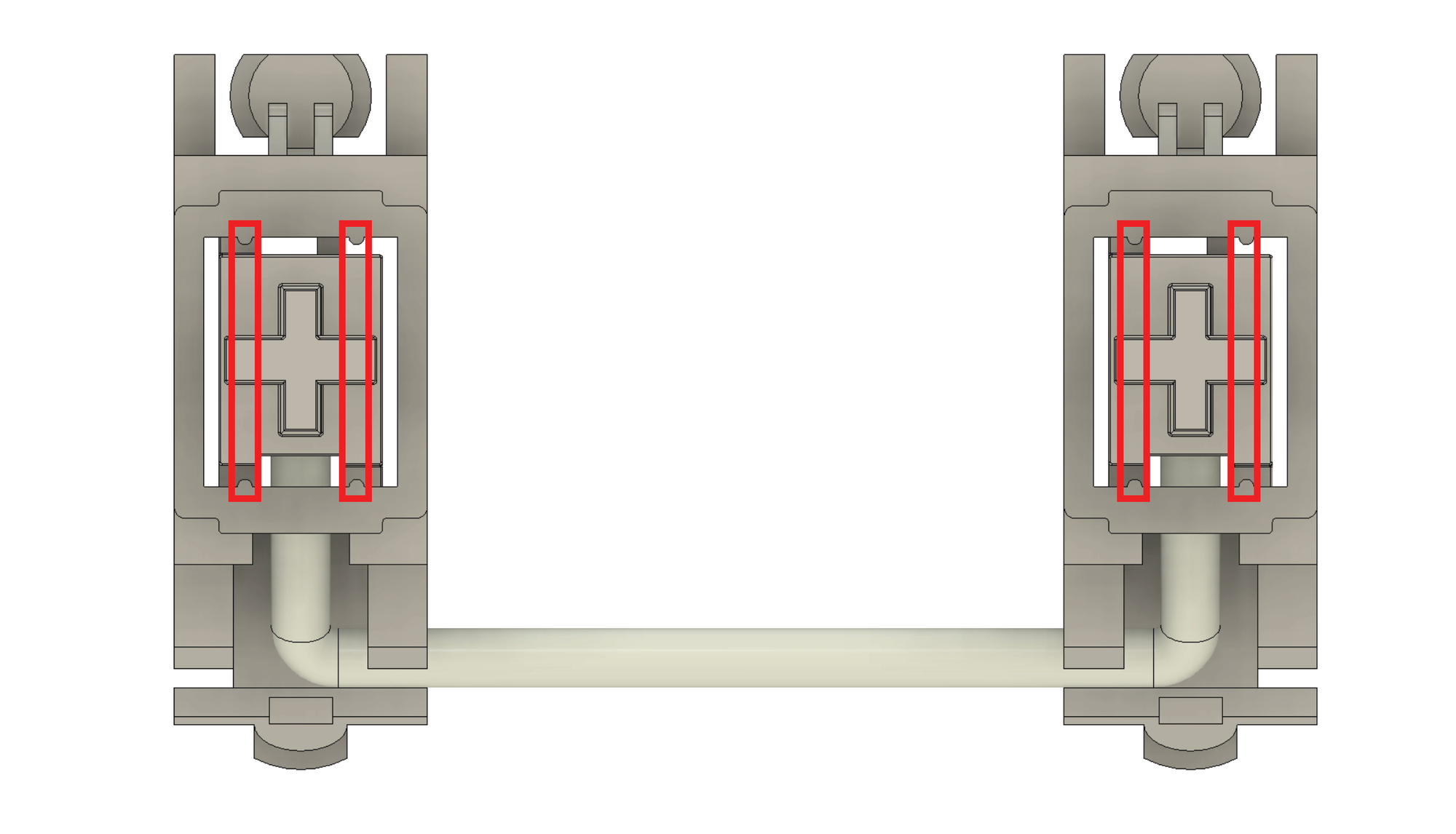
Normal Cherry stabilizers have a number of pairs contact surfaces that act as kinematic freedom locks, some of which are shown below. A number of these are redundant over-constraints, but all of their contact faces traverse relatively long distances. Some of the critical ones are highlighted below.
Our stabilizer relocates the contact faces that restrict the same degrees of freedom to small tongue-in-groove interfaces, one on each side of the stabilizer. These features are many times closer than the corresponding pairs of faces shown above.
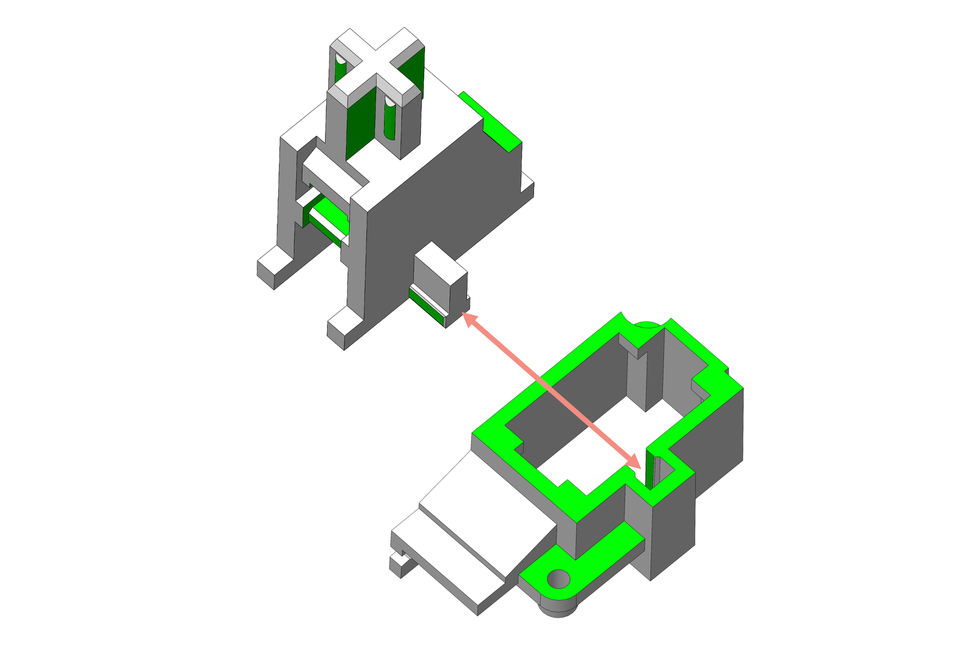
There are two significant aspects to this change in geometry. Firstly, by using a smaller interface to constrain movement, we're able to control tolerances better, allowing for markedly smaller—nearly zero-clearance—gaps between slider and housing, minimizing the chance of ticking. (The underlying principle is that, when the cost/difficulty of manufacturing is held constant, factories can deliver significantly tighter tolerances over smaller dimensions compared to larger ones, so smaller dimensions are always inherently tighter-tolerance.) Secondly, the new configuration optimizes bearing ratio to the maximum extent possible—at least within the challenging constraints of the application.
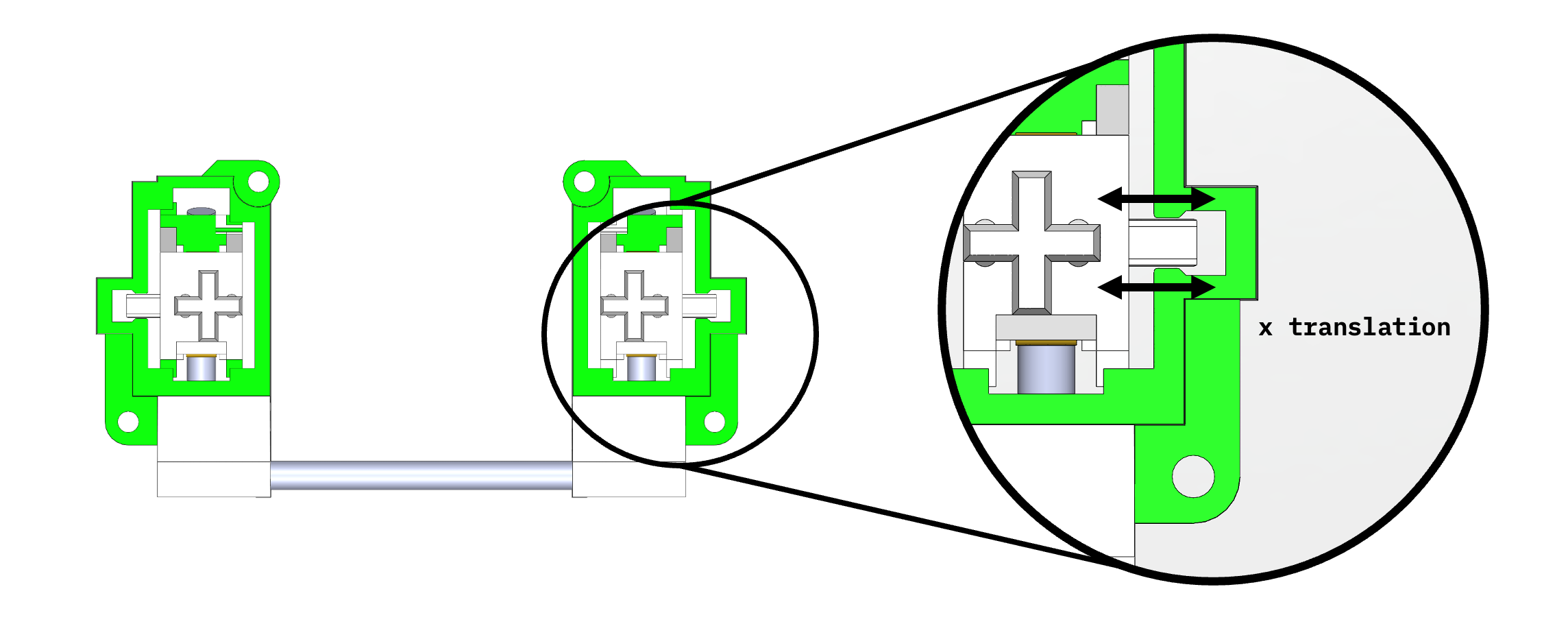
The new interface also allows for free side-to-side translation of the sliders, meaning that we can now accommodate a wide range of keycap stem spacing variations, as the sliders can move slightly inward or outward without interacting with any other constraining surfaces.
These and other kinematic optimizations to remove over-constraints made possible the addition of two compliant sub-mechanisms within the larger more traditional ("rigid body") design. First among these, and significant to elimination of one source of ticking, was the use of a preload beam pressing against the rotating arm of the wire linkage. (Preload, in the context of bearings, refers to applying a force to the bearing to prevent any clearance gaps between its mating surfaces.) Here a compliant/flexible beam is molded into the stabilizer housing, pressing the wire against an opposing face in its clip. Some measure of simulation and experiment needs to be done to get the forces just right to prevent binding, but, when properly calibrated, preload can completely eliminate the rattle/ticking noise that would come from gaps between parts in a bearing.

My prior design required a 0.3mm clearance between wire and housing to prevent binding but, due to the kinematic optimization, this preload beam was able to be added, moving us instead to a zero clearance (i.e., completely noise-free) interface.
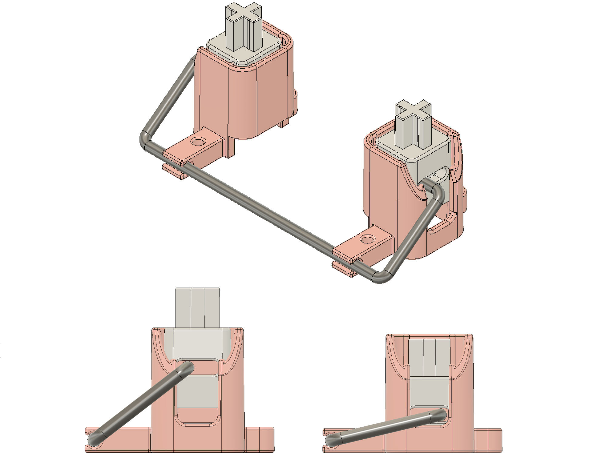
This concept was further extended to the critical wire-to-slider interface, which is the cause of stabilizer rattle—the main problem we're trying to solve. For this, a preload beam in the form of a metal spring is clipped into the slider. It hangs down from the slider ceiling and presses down on the stabilizer wire from above, gently preloading the wire against the floor the slider and preventing any gap between those two, at all points of the stabilizer's travel. Brass was chosen for this preload spring for its good sliding properties against stainless steel. (We didn't end up choosing a molded-in plastic beam like we did on the wire clip, due to concerns about long-term material creep under load with this relatively highly cantilevered beam.)

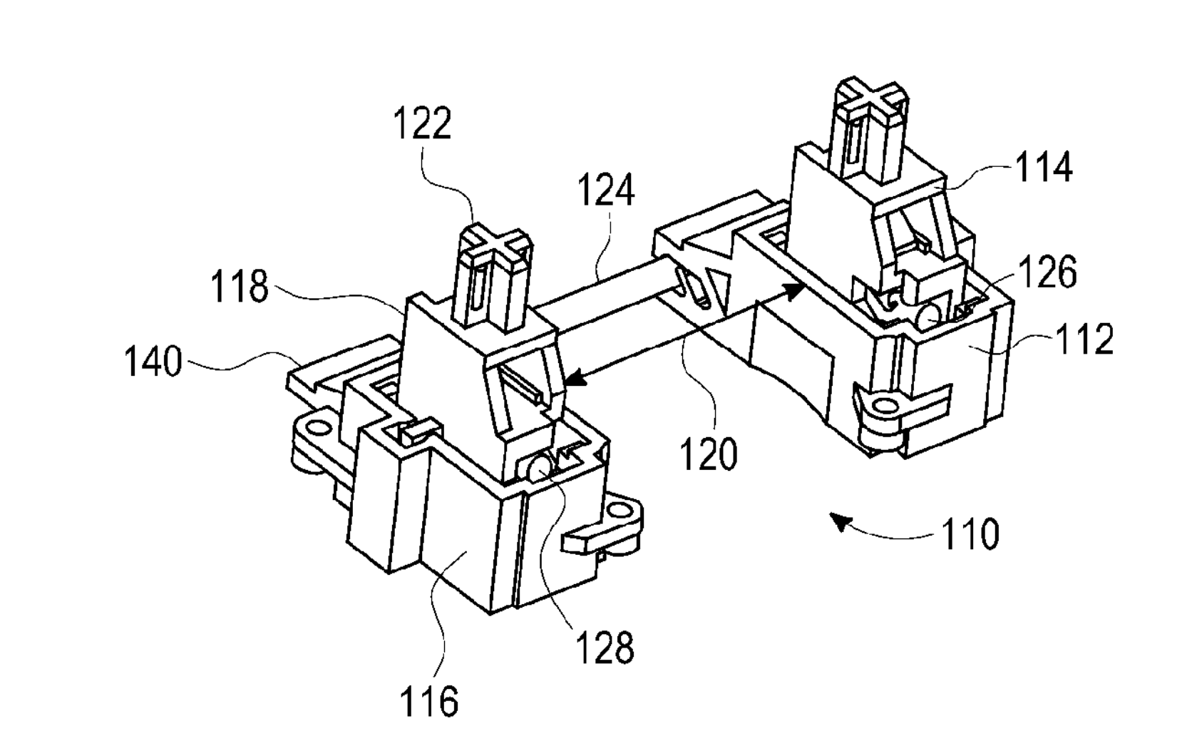
Note that above CAD models show the brass preload spring appearing to penetrate into the wire surface, but that's only because the spring has to be manufactured to extend beyond the wire's location when not loaded. This way it can deflect upward when loaded and apply a downward force. Of course, when installed in reality, the preload spring flexes upward and physically rests on top of the wire, as shown in 138 in our patent drawing below.

Here, then, we have the full mechanism with all its functional aspects outlined. You can read the detailed US Patent here.
This video demonstrates the all-important zero-gap (and thus zero rattle) relationship between wire and slider, using one of our 3D printed prototypes. This and every aspect of the performance of this stabilizer design were amazing.
This was all well and good. Truly astonishing in fact. But the careful reader will note that the only visualizations of this design I have are either CAD models or 3D printed prototypes, not production parts.
Over a year ago, I was on the verge of pulling the trigger on production tooling for this design, which would have involved a massive financial commitment and some level of lock-in. That is when I started having trouble sleeping.
Remember how I said "almost zero clearance" when referring to the tongue-in-groove interface—and used the term minimize with respect to ticking at that location? By this point, our project costs had already pushed into the six figures, and I found myself with another 90%-successful improvement relative to my first, already 90%-successful, attempt. I showed a rough 3D printed prototype to Taeha himself and he was impressed, and I was fairly certain almost everyone would have been wowed by a production version of the design.
But, when I could sleep, I kept having dreams of that moonshot design we had passed up for fear of its risk and complexity. I couldn't stop from wandering back to that intricate watch-maker's design, with the complex articulated pin joints and radically different approach to the problem. I kept thinking about the old Steve Jobs point about how being trapped in old paradigms can limit your vision—how the first decades of television involved basically pointing a camera at a radio show. Was that what I was doing here?
The thing is that this project—and my work in keyboards in general—is about my nostalgic admiration for early pioneers of personal computing like Jobs and their of iconoclastic revolutionary reinvention, and I feel like every part of it needs to be worthy of those values. Jobs himself held back release of the iPhone, Toy Story, and the first Apple Store at the very last minute when he had similar intuitions about each not being quite as good as they might be. In each case, the delay was highly problematic from a short-term business perspective, but it was also creatively the right thing to do (which I believe is always, in the long term, also the right business decision).
After enough of these sleepless nights, I called up my (now much beloved) pals in Copenhagen and summoned us all together back to the drawing board.
Act III: Utopian Reinvention—the Norbauer-type stabilizer
A tricky thing with a perfect kinematic score is that it's hard to improve. But there is more to an optimal stabilizer than just deleting over-constraint. There remained the problem inherent in all sliding linear bearings: the bearing ratio. Quality of a sliding bearing is ultimately related to the length of the slide, but we want keyboards to be as flat as possible, which necessarily limits slider travel distance, and there is only so much we can escape this basic problem with a linear slider. There are also limitations in injection molding as a manufacturing process, limiting the precision (and thus tightness of fit) to which two mating plastic parts, such as the tongue and the groove, can be manufactured. These concerns left us with a still non-zero nominal gap between the sliding faces of our functional interface and thus the possibility of subtle ticking. To reach perfection and effectively zero clearances everywhere, we would need to transcend the existing stabilizer paradigm and reformulate the problem on our own terms. The Norbauer-type stabilizer does that by taking the two-dimensional problem of linear sliding and cleverly projecting it into three-dimensional space, using a set of hinge leaves that fold and nest into each other, effectively lengthening the bearing. This is its core insight. But the advantages of the pin joint architecture are many and subtle.
There are thirteen types of generic joints in mechanical engineering, but there is a design rule of thumb related to joint selection: whenever you can use a pin joint, do. There are many reasons for this, depending on the application, but in our case one of the most compelling is that it would allow us remove an injection molded part from each mating surface, replacing it instead with a metal pin. Precision metal pins are manufactured using a rolling and grinding process, making them massively more dimensionally accurate and uniform compared to injection molded parts. The interface tolerances of joints employing them can become much tighter as a result, allowing for effectively zero clearance at all interfaces and thus the total elimination not just of rattle but ticking. For 4mm of switch travel, we are moving our parts very little about tiny pins compared to the length of 4mm slide, making it effectively a gearing rather than a simple 1:1 ratio as with the slider. The math works out such that we experience 1/10th of the friction compared to a sliding joint. Using a plastic-to-steel pairing is a further significant reduction in friction compared to the prior plastic-on-plastic slide.
When dealing with flat sliding surfaces like in the tongue-in-groove, we were also exposed to natural manufacturing variations not just in dimensional terms but also geometric ones (issues of flatness, straightness, etc.) By converting our design to use only pin joints, we eliminate large planar faces and thus one significant source of variation.
In the one spot we have a joint that isn't a perfect pin type, the clip in the housing that holds the rotating wire. For that, we use a preload beam molded into the housing pressing against the wire to ensure zero clearance at all times. If you assemble a switch in a test fixture with a normal stabilizer and shake it, it makes a great deal of noise. If you assemble a Norbauer-type stabilizer into the same and shake it, it is entirely silent.
Our mechanism has two stabilizing sub-systems at transverse axes. By essentially adding a second stabilizer in this way, the Norbauer-type stabilizer also actually performs the anti-seesaw function better than traditional solutions as well.
It is, by all my established criteria, the perfect stabilizer.
This all comes at a considerable cost, of course, and I'm not just talking about the development expenses. A single stabilizer of the Norbauer type takes about half an hour to assemble. The large number of precision injection molded parts also means very high tooling cost, and these parts require a number of side actions and other details that significantly increase the cost and difficulty of injection molds, requiring us to work with more expensive and sophisticated high-production factories. But, from a development perspective, the most challenging aspect of the design was the extremely confined work envelope. The volume of each stabilizer tower is around 1 cm³, and the overall assembly must contain 21 parts, 10 of them living in each of those towers. For an injection-molded consumer product, this is a crazy level of part density. Many design features, such end stops for keycap installation/removal, etc. are also not separate parts but are geometry molded into parts that serve other functions (such as the housing) and aren't considered in the 21 part count but nevertheless needed to be fit into this miniscule space. There are also many nuances to how you get the hinge leaves to work together without getting into positions that can lock up. RD8's work on all this design was thus absolutely heroic. It was a design I could never have contemplating creating on my own.
Had I known it would take me this much money and five years, I might have walked out a window rather than embark on the project. I am grateful to my ignorance and optimism for having nudged me out the door, but also the awe-inspiring forces of happenstance and path-dependent chaos. If any of a million coin tosses in the messy process above had landed another way, I would never have ended up where I did.
Coda: the ninety-ninety rule
In the 1980s software engineer Tom Cargill of Bell Labs coined the Ninety-ninety "rule" (a joke, really) to describe a common problem in project management. It originally referred specifically to coding, but it can be generalized as follows:
The first 90 percent of a project's progress accounts for the first 90 percent of the development time. The remaining 10 percent of progress accounts for the other 90 percent of the development time.
I often put it this way: most projects seem 90% done for 90% of their duration. This creates a sort of asymptotic calculus problem where you always seem to be approaching but never quite reaching the finish line, as delving into each fractal "last 10%" layer exposes a new universe of previously unfathomable problems and delays. We might call it a corollary of Hofstater's Law: "It always takes longer than you expect, even when you take into account Hofstadter's Law."
Every significant project that I've ever done (that in retrospect seems having been worth doing) has been like this. The only solution I know of is simply to embrace going slowly and not to get too caught up in my expectations (blindingly optimistic imaginings) for when a project is going to be done. Extremely hard projects with these fractally expanding timelines are, in my experience, the ones that it is important to undertake. They're the ones most others won't be willing or able to tackle. In business, this is where moats come from. In art, it's where achievement comes from. And in life in general, much of the satisfaction. I tend to groan, fret, and lose sleep at every step in the process, but I don't think I would have it any other way. Now all I have to figure out is what keyboard impossibility I want to keep me up at night next.